Language
 English
 русский
 Español

Get A Quote
Get A Quote
 Home / News / Industry News / How Welding Robotic Arms, LSN Nut Conveyors, and FN Seam Welding Machines Build Smarter Production Lines
 2026.07.23
 Industry News
Machine welding definition, in practical terms, refers to a joining process where mechanical or programmable equipment controls the arc, pressure, or seam path instead of a person holding a torch or gun by hand. The operator sets parameters once, the machine repeats them thousands of times, and the result is a joint whose strength and appearance do not drift from the first part to the ten thousandth. This is different from manual welding, where fatigue, hand tremor, and inconsistent travel speed create variation from one weld to the next.
In a factory context, machine welding usually shows up in three forms: robotic arc or spot welding cells, fixed-position resistance welders, and continuous seam welders. Each has a different role. A robotic arm handles complex, three dimensional joint paths. A resistance or seam welder handles flat, repeatable joints at high speed. A conveyor or feeder system keeps small hardware, such as nuts or studs, moving into position without a worker reaching into a fixture by hand. When these three categories are combined into one line, the plant gains a level of repeatability that manual stations cannot match.
The welding robotic arm is the component most people picture when they hear "automated welding." It is a multi axis manipulator that carries a torch, gun, or electrode holder along a programmed path, repeating the same motion within a fraction of a millimeter each cycle. Unlike a fixed welding head, the arm can reach around corners, tilt into awkward angles, and switch between multiple weld programs without retooling.

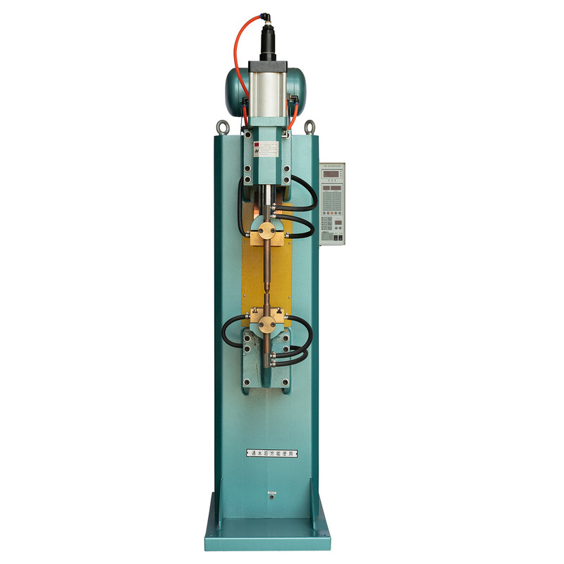
A robotic spot welding cell is typically justified when a part has more than a handful of repeat welds per cycle, when the joint geometry is three dimensional, or when the weld location is difficult for a person to reach consistently over a full shift. Sheet metal frames, chassis components, brackets, and enclosures are common candidates because they combine multiple short welds across several planes.
| Misconception | Practical Reality |
|---|---|
| Robotic arms only suit high volume production | Cells with quick program changeover also support mixed, lower volume batches |
| Programming requires a dedicated engineer every time | Many teach pendants and offline programming tools allow trained operators to adjust paths |
| Robotic welding removes the need for quality checks | Consistent output still needs periodic dimensional and visual inspection |
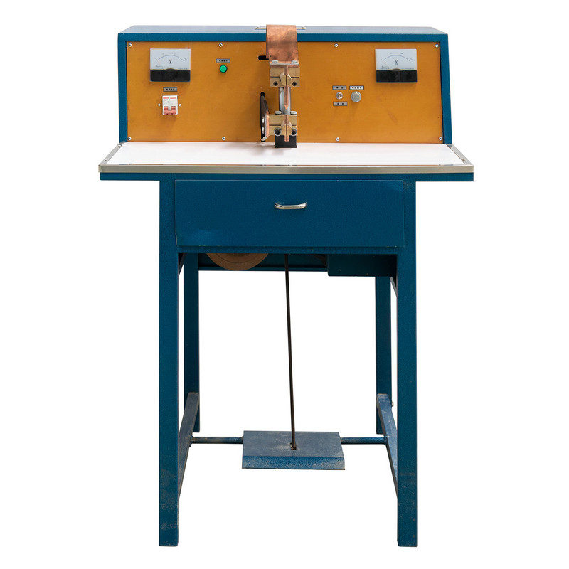
Fastener handling is an easy step to overlook, yet it is one of the most frequent causes of line stoppages in assembly and welding operations. An LSN nut conveyor addresses this by sorting, orienting, and delivering nuts through a vibratory or track based path so that a robotic arm, weld nut gun, or manual station always receives a correctly oriented part at the exact moment it is needed.

An automatic nut feeder built around a conveyor track typically performs four jobs in sequence: bulk storage, orientation sorting, single piece separation, and delivery to the weld point. Because these steps happen mechanically, the line does not depend on an operator manually picking and placing small hardware, which is both slow and a common source of missed or double fed parts.
| Manual Nut Feeding | Conveyor Fed Nut Delivery |
|---|---|
| Operator picks and orients each nut by hand | Track orientation happens automatically before delivery |
| Feed rate limited by operator fatigue and attention | Feed rate matched to the weld cell cycle time |
| Higher risk of missed or double fed parts | Sensors confirm single piece delivery before each cycle |
When paired with a robotic arm, the conveyor essentially becomes the arm's supply chain. If the feeder stalls, the whole downstream weld cycle stalls with it, so feeder reliability is often the deciding factor in whether an automated line hits its daily output target.
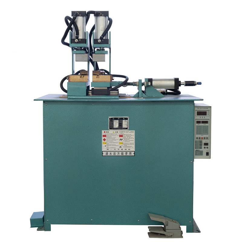
Where the robotic arm and nut conveyor handle discrete, point by point joints, an FN seam welding machine is built for a different task: producing a continuous, overlapping series of resistance welds along a joint line, forming what is effectively a leak tight or structurally continuous seam. This is the standard approach for tanks, ducting, drums, and other parts that need a sealed or uniformly strong edge rather than a series of individual spot welds.

Controls how much overlap forms between successive weld nuggets along the seam.
Determines nugget penetration and helps prevent expulsion at the seam edge.
Affects electrode wheel life and consistency across long production runs.
Continuous seam welding is judged less by individual weld strength and more by uniformity across the full length of the joint. A seam with even nugget spacing and consistent overlap resists leaks and stress concentration far better than one with irregular pitch, even if the strongest individual point in each seam is similar.
The value of combining these three machine types shows up most clearly when they are mapped as a single flow rather than treated as separate stations. A typical integrated cell might move a part from raw material staging, through fastener delivery, into robotic joining, and finally through seam finishing and inspection.
Feeder and robotic stations are usually the two points worth monitoring most closely, since a stall at either one halts everything downstream of it. Seam welding and quality check stations tend to run on a steadier cycle once fed a consistent supply of joined parts.
The table below reflects general patterns reported across automated resistance welding lines rather than any single facility, and is meant as a planning reference rather than a guarantee.
| Method | Typical Joint Type | Best Suited Volume | Operator Involvement |
|---|---|---|---|
| Manual arc or spot welding | Point or short seam | Low to moderate | Continuous, hands on |
| Robotic arm welding cell | Multi point, 3D path | Moderate to high | Loading, monitoring, changeover |
| Continuous seam welding machine | Long, uniform seam | High, repeat parts | Setup and periodic checks |
Welding Factory Automation Automated Resistance Welding Lines Robotic Spot Welding Cell
Automated welding equipment earns back its cost through uptime, not just raw cycle speed. A line that runs fast but stops twice a shift for jammed feeders or misaligned electrodes will underperform a slightly slower line that runs without interruption. Three habits tend to separate reliable lines from unreliable ones.
Training also matters as much as the hardware itself. Operators who understand why a feeder jams or why a seam weld pitch drifts can correct minor issues before they escalate into full stoppages, which keeps the automated welding line closer to its designed output over a full production year.
A robotic arm moves a torch or gun along a programmed path across multiple axes, which suits complex or three dimensional joints. A fixed resistance welder applies pressure and current at set points or along a fixed seam path, which suits flat, repeatable joints at high speed.
Manual placement is slower, more prone to missed or double fed parts, and limited by operator fatigue over a shift. A conveyor based feeder maintains a consistent feed rate matched to the weld cycle and reduces the chance of misfeeds.
Continuous seam welding produces overlapping weld nuggets that form a uniform, often leak resistant seam, while individual spot welds leave gaps between joints. Seam welding is preferred where sealing or continuous structural strength matters more than isolated joint strength.
Feeder jams and robotic positioning drift are the two most common causes reported across automated lines. Both are typically addressed through scheduled inspection intervals rather than reactive repairs after a stoppage.
Yes, provided the cell supports quick program changeover between part numbers. This depends more on programming and fixture flexibility than on the robotic arm hardware itself.
Recommended Products

Product
Contact Info.
+86-152-5712-5882
Fax: +86-563-2269966
No. 21 Guangping Road, Guangde Economic Development Zone, Guangde City, Anhui Province
QR Code