Language
 English
 русский
 Español

Get A Quote
Get A Quote
 Home / News / Industry News / How Regular Maintenance of Welding Electrodes and Controllers Prevents Costly Downtime
 2026.07.30
 Industry News
In resistance spot welding, the quality of every joint depends on two components working in sync: the electrode that delivers current and pressure to the workpiece, and the controller that governs how much current flows and for how long. When either component drifts out of condition, the symptoms rarely announce themselves clearly. Instead, operators see inconsistent nugget size, occasional expulsion, or welds that pass visual inspection but fail destructive testing.
A welding electrode is a consumable part by design, and treating it as such—rather than waiting for outright failure—is the single most cost-effective habit a welding line can adopt. Field data from production audits commonly shows that up to 30 percent of weld rejects trace back to electrode face degradation rather than material or fixture issues. Pairing disciplined electrode care with routine welding controller verification closes most of that gap without capital investment.
Key point: Electrode wear and controller drift compound each other. A pitted electrode face increases contact resistance, which the controller cannot compensate for unless it is calibrated to detect the shift.
To understand what is the electrode in welding, it helps to separate its two jobs. First, it clamps the sheets together with controlled force so the faying surfaces make intimate contact. Second, it conducts a short, high-amperage pulse through that contact point, generating localized resistance heat that forms the weld nugget. Because the electrode tip sits directly in the heat and current path, it experiences thermal cycling thousands of times per shift.
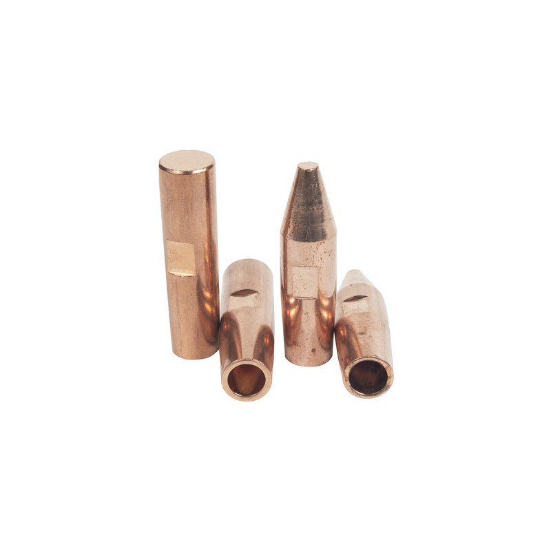
Most production electrodes are made from copper alloys chosen for a balance of electrical conductivity and mechanical hardness at elevated temperature. Pure copper conducts extremely well but softens too quickly under repeated thermal cycling, so alloying elements are added to slow deformation while keeping resistivity low. As a consumable welding electrode ages, three wear mechanisms typically appear:
Each of these mechanisms raises electrical resistance at the tip, which shifts heat generation away from the intended nugget location and toward the electrode-to-sheet interface, accelerating further wear in a feedback loop.
Recognizing the visual signature of a failure mode shortens diagnostic time considerably. The table below summarizes patterns seen across general manufacturing environments.
| Failure Mode | Visual Indicator | Likely Cause | Corrective Action |
|---|---|---|---|
| Mushrooming | Flattened, widened tip face | Excessive force or heat cycling | Dress or replace tip; verify force setting |
| Pitting | Small dark craters on face | Current spikes or arcing | Check controller current stability |
| Alloying / sticking | Discoloration, sheet material transfer | Coating material bonding to tip | Clean or dress face; adjust hold time |
| Misalignment | Off-center wear pattern | Bent grip rod or fixture drift | Inspect and realign grip rod assembly |
| Cracking | Visible surface fractures | Thermal fatigue over service life | Replace electrode immediately |
Spot welding tips dressers restore the original tip geometry without requiring a full electrode swap, extending service life considerably when applied at the right interval. Waiting too long between dressing cycles allows wear to progress past the point where dressing alone can recover consistent nugget formation.
A practical guideline used in many shops is to dress tips after a set number of weld cycles rather than waiting for visible defects, since resistance drift often precedes visible wear by a meaningful margin.
The welding controller governs squeeze time, weld time, current level, and hold time for every cycle. Welding controller programming errors or drift in current feedback sensors are among the more overlooked causes of weld variation, largely because the controller display can continue to show a stable setpoint even as actual delivered current shifts due to electrode resistance changes.
Allows electrode force to stabilize before current begins, preventing expulsion at the start of the cycle.
Duration current flows through the joint; too short under-fuses the nugget, too long risks expulsion.
Maintains force after current stops so the nugget solidifies under pressure.
Routine calibration checks should confirm that the controller's programmed values match what is actually delivered at the electrode tip, since sensor drift over months of operation is common in high-cycle environments. A basic verification schedule includes:
The welding transformer steps down line voltage while stepping up current to the level needed for resistance welding. Because it handles very high secondary currents in short pulses, insulation breakdown and cooling issues are the primary concerns during resistance welding transformer repair.

Common inspection points include:
| Inspection Point | What to Check | Warning Sign |
|---|---|---|
| Cooling circuit | Water flow rate and temperature rise | Reduced flow, elevated coil temperature |
| Secondary connections | Tightness and surface condition | Discoloration, arcing marks |
| Insulation | Resistance readings between windings | Declining insulation resistance over time |
When insulation resistance falls below an acceptable threshold or cooling cannot keep coil temperature within a safe range despite corrected flow, replacement is generally more economical than continued repair, since intermittent transformer failures are difficult to diagnose once production resumes.
The welding grip rod holds the electrode in position and transmits clamping force from the weld head. Even a well-maintained electrode will wear unevenly if the grip rod holding it is bent, loose, or misaligned, so grip rod condition deserves equal attention within any general welding accessories maintenance routine.
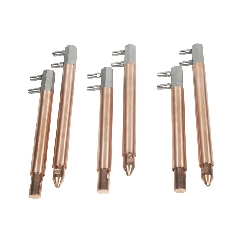
Welding grip rod replacement typically follows this sequence:
A quick alignment check—confirming both electrode tips meet squarely at center—prevents the off-center wear pattern that otherwise shortens electrode life regardless of how well the tip itself is maintained.
| Component | Daily | Weekly | Monthly |
|---|---|---|---|
| Electrode | Visual face check | Dress or measure wear | Review replacement log |
| Controller | Alarm log review | Compare setpoint vs output | Full calibration check |
| Transformer | Cooling flow check | Connection tightness check | Insulation resistance test |
| Grip Rod | — | Alignment check | Wear and play inspection |
When weld quality drops, working through components in a consistent order avoids wasted time chasing the wrong cause.
Interval depends on material thickness, coating type, and cycle count, but many production lines dress tips at a fixed cycle count and replace them once dressing no longer restores consistent nugget size.
Recalibration can compensate temporarily by adjusting current, but it does not correct the underlying resistance change at a worn tip. Addressing the electrode directly is the more durable fix.
It also applies and maintains clamping force throughout the weld cycle, which is why mechanical condition matters as much as electrical condition.
Gradual increases in coil temperature during normal cycling, or a declining trend in insulation resistance readings over successive tests, are typically the earliest indicators.
Yes. Misalignment shifts pressure distribution across the tip face, producing uneven wear and inconsistent nugget formation even before visible electrode damage appears.
Recommended Products

Product
Contact Info.
+86-152-5712-5882
Fax: +86-563-2269966
No. 21 Guangping Road, Guangde Economic Development Zone, Guangde City, Anhui Province
QR Code



