Language
 English
 русский
 Español

Get A Quote
Get A Quote
 2026.08.07
 Industry News
Every resistance spot weld is, at its core, a controlled thermal event. A brief, intense pulse of current passes through two overlapping metal sheets, and the resistance at their interface generates enough heat to fuse them together in a fraction of a second. What operators rarely think about is where all of that heat goes once the weld is made. It does not disappear. It radiates into the electrodes, into the transformer, into the surrounding frame, and eventually into the ambient air of the production floor.
On a single weld, this is a non-issue. On a production line running several thousand welds per shift, the accumulated thermal load becomes the single largest constraint on machine output. Electrode tips mushroom out of shape faster than expected, transformer windings run hotter than their rated tolerance, and control cabinets start throwing thermal faults during the busiest hours of the day. A properly sized chiller is what keeps this thermal load from becoming a production problem rather than a background nuisance.
The relationship between heat and weld quality is not linear. As electrode temperature climbs past its stable operating range, contact resistance at the tip begins to fluctuate weld to weld, which shows up downstream as inconsistent nugget size, expulsion, and sheet marking. Thermal management is therefore not a housekeeping task bolted onto the welding process. It is a functional part of the weld quality system itself, and it deserves the same engineering attention as electrode force or current programming.
Before sizing any cooling equipment, it helps to understand how much electrical energy a spot welder actually pulls from the supply, because welder amperage draw is the single best predictor of how much heat the system will generate. This is a question operators ask constantly: how many amps does a welder draw compared with other shop equipment they already run on the same circuits? The answer varies widely by machine class, duty cycle, and electrode force, but general patterns hold across the industry.
A light pedal-operated spot welder used for sheet metal enclosures or small brackets typically pulls a modest primary line current, since its secondary current pulses are short and its duty cycle is low. A medium bench-mounted unit used in general fabrication draws considerably more, reflecting its larger transformer and higher secondary current output. Heavy industrial multi-spot systems used in automotive body assembly draw the most by a wide margin, because they run near-continuous cycling across multiple welding heads.
For context, it is useful to compare welder amp draw against a completely different category of shop tool. A high speed sander pulls a small, steady current with no cycling spikes at all, since it is a continuous-duty motor rather than a pulsed resistive load. Placing the two side by side on a chart makes clear why welders, unlike sanders, need dedicated circuit planning and active cooling rather than passive air convection alone.
The gap between the sander and the heavy multi-spot system illustrates why cooling infrastructure planning has to be matched to machine class rather than treated as a single generic spec. A facility mixing several welder types on one cooling loop needs to size that loop around its heaviest draw units, with headroom for simultaneous operation, not around an average.
Most industrial spot welding installations rely on a closed loop cooling system rather than once-through tap water, both for consistency and for environmental reasons. In a closed loop, the same coolant circulates continuously between the welder and the chiller, exchanging heat with ambient air or a secondary water circuit at the chiller rather than being discharged to drain. The coolant itself is typically a treated water or water-glycol mixture chosen to resist scale formation and biological growth inside narrow electrode passages.
The basic cycle is straightforward to follow, even though the equipment inside it is engineered to fairly tight tolerances. Coolant enters the welder at a controlled supply temperature, absorbs heat as it passes through the electrode holders, transformer housing, and control cabinet, then returns to the chiller warmer than it left. The chiller extracts that heat and sends the coolant back out at its set temperature, and the cycle repeats continuously through the shift.
Three factors determine whether this loop actually holds a stable temperature under production load: the chiller capacity relative to peak heat rejection, the flow rate through the electrode passages, and the thermal mass of the reservoir buffering short-term spikes. Undersizing any one of these three lets the coolant supply temperature drift upward over the course of a shift, which is exactly the failure mode operators notice as gradually degrading weld consistency in the afternoon compared with the morning.
Not every spot welder uses active liquid cooling. Light-duty units with low duty cycles often rely on natural convection and a finned heat sink around the electrode holders, which is adequate as long as the welder is not asked to run continuously. Once production volume rises past a certain threshold, a water cooled spot welder becomes the more practical choice, because liquid coolant carries heat away from the tip far more efficiently than still air ever can.
The tradeoff is added complexity. A water cooled spot welder needs plumbing, a chiller or water source, periodic coolant maintenance, and monitoring for leaks or blockages that an air cooled unit does not. In exchange, it supports substantially higher duty cycles, longer continuous run times, and more stable electrode temperatures over the course of a shift, which matters directly to throughput and weld repeatability on any line running above light-duty volumes.
| Factor | Air cooled welder | Water cooled welder |
|---|---|---|
| Typical duty cycle | 10 to 25 percent | 40 to 80 percent |
| Electrode temperature stability | Drifts under sustained load | Holds within a narrow band |
| Best suited volume | Low volume, intermittent | Medium to high volume, continuous |
| Maintenance scope | Minimal, dust and airflow checks | Coolant, filters, pump, chiller service |
| Upfront equipment cost | Lower | Higher |
Facilities weighing this decision usually find that the additional investment in an industrial water chiller for welding pays for itself once the welder is running enough shifts that electrode replacement frequency and rework from inconsistent nuggets start showing up as recurring line items. Below that volume threshold, the simpler air cooled configuration remains the more sensible choice.
Sizing a chiller correctly means looking beyond the nameplate rating of the welder and considering how heat load actually behaves across a full shift. A welder that runs intermittently with idle gaps between batches produces a very different thermal profile than one running continuous back-to-back cycles on an automated line. An undersized chiller can keep pace during the first hour of a shift and then progressively lose ground as the reservoir accumulates heat faster than the chiller can reject it.
The chart below illustrates a representative pattern across an eight hour shift, comparing coolant supply temperature with an adequately sized chiller against a system operating without one, relying only on ambient convection through an open tank.
With a properly sized chiller, supply temperature stabilizes after the first hour and holds within a narrow band for the remainder of the shift. Without one, temperature climbs steadily and never plateaus, which is the mechanism behind afternoon shift quality drift that many production teams notice without immediately connecting it to coolant performance.
A correctly sized chiller only delivers its full benefit when paired with routine spot welding machine maintenance. Coolant that sits unchanged for months accumulates mineral scale and biological growth inside narrow electrode passages, gradually restricting flow even though the chiller itself is functioning normally. This is one of the more common causes of gradual overheating that gets misdiagnosed as a chiller fault when the actual restriction is downstream in the welder's own cooling channels.
The pattern across these five dimensions is consistent with what most maintenance logs show in practice: chilled systems trade a higher maintenance workload for meaningfully longer electrode life, higher sustainable duty cycle, and more consistent weld outcomes, which in most production environments is a favorable exchange once volume justifies it.
Unplanned downtime is where the cost of inadequate cooling becomes most visible on a production report. The chart below compares average monthly downtime hours attributable to thermal issues across three common cooling configurations, based on patterns typical of multi-shift fabrication environments.
A drop from fourteen hours to two hours of monthly thermal downtime is not an incremental gain. Across a full year, that difference represents multiple additional production days recovered purely by matching cooling capacity to actual machine load.
In a well laid out production cell, the chiller sits close enough to the welding station to minimize coolant line length, which reduces both pressure loss and the volume of coolant that must be temperature-controlled. Longer runs between chiller and welder introduce more opportunity for heat gain in the supply line and pressure drop that reduces flow rate at the electrode tips, both of which work against the cooling system's intended purpose.
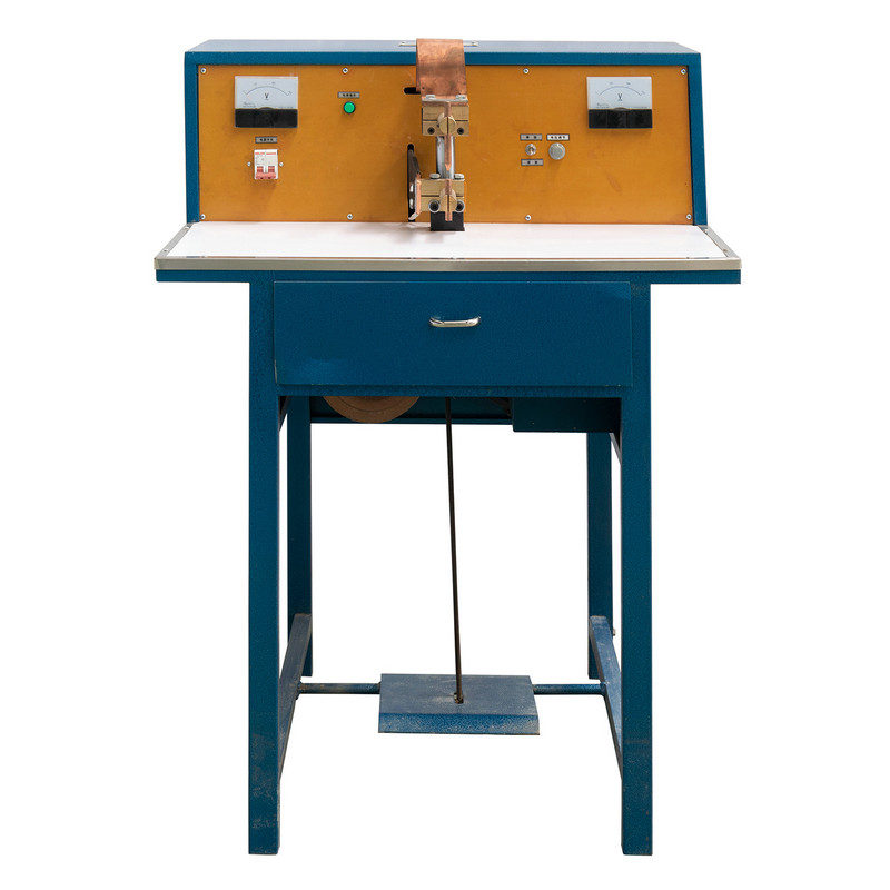
A spot welding machine configured with dedicated coolant supply and return lines
Reservoir placement also matters more than it might appear. A reservoir positioned where it receives significant radiant heat from the welder's own transformer works against the chiller rather than with it, forcing the chiller to fight an additional heat source that better placement would have avoided entirely.
It depends heavily on the machine class. A light pedal spot welder typically draws in the range of 20 to 35 amps, a medium bench unit closer to 40 to 55 amps, and a heavy industrial multi-spot system can reach 60 to 100 amps or more. This is substantially higher than continuous-duty tools like a high speed sander, which usually draws under 10 amps, because welders deliver short high-current pulses rather than a steady load.
No. Light-duty welders with low duty cycles and intermittent use often operate reliably with air cooling alone. A chiller becomes worthwhile once duty cycle, welding frequency, or continuous run time rise to a point where natural convection can no longer keep electrode and transformer temperatures within a stable range.
An open loop draws fresh water and discharges it after a single pass, which wastes water and offers no temperature control beyond incoming supply conditions. A closed loop recirculates the same coolant continuously through a chiller, holding a consistent supply temperature and avoiding continuous water consumption.
This varies with coolant type and operating conditions, but most facilities test concentration and clarity on a monthly basis and plan a full coolant change at least once or twice a year, more frequently in harder water conditions or high-usage environments where scale accumulates faster.
Gradually increasing coolant supply temperature over the course of a shift, inconsistent weld nugget size later in the day compared with the morning, and more frequent electrode dressing or replacement are the most common early indicators that cooling capacity is not keeping pace with production load.
Recommended Products

Product
Contact Info.
+86-152-5712-5882
Fax: +86-563-2269966
No. 21 Guangping Road, Guangde Economic Development Zone, Guangde City, Anhui Province
QR Code