Language
 English
 русский
 Español

Get A Quote
Get A Quote
 Home / News / Industry News / How Do Pedal and Pneumatic Spot Welding Machines Compare for Sheet Metal Production?
 2026.08.13
 Industry News
Resistance spot welding equipment is generally divided by how the electrode force is generated and applied. Mechanical foot-pedal units rely on the operator's leg motion transferred through a lever or gear system, while pneumatic units use compressed air cylinders to deliver consistent, repeatable clamping force. Understanding this distinction matters more than most buyers realize, because the force delivery method directly affects nugget formation, splash, and electrode life across thousands of weld cycles.
A piece of spot welder equipment is typically chosen based on three factors: material thickness range, expected daily cycle count, and the skill level of the operator. Lighter gauge sheet metal in low-volume repair work often suits mechanical pedal units, while continuous production lines benefit from the pressure stability that pneumatic cylinders provide.
| Category | Force Source | Typical Material Thickness | Best Fit |
|---|---|---|---|
| Mechanical Pedal | Foot lever / gear reduction | 0.3mm - 1.5mm | Repair shops, small batch runs |
| Gear-Type Pedal | Geared lever mechanism | 0.3mm - 2.0mm | Mixed-gauge fabrication |
| Pneumatic | Compressed air cylinder | 0.5mm - 3.0mm | Continuous or high-volume lines |
The DN Pedal Spot Welding Machine represents the traditional mechanical category, where the operator controls both timing and pressure through direct foot pressure. This design gives skilled operators fine control over dwell time on irregular or thin panels, which is valuable when working on curved automotive body sections or small appliance housings where an automated cycle might overheat delicate material.
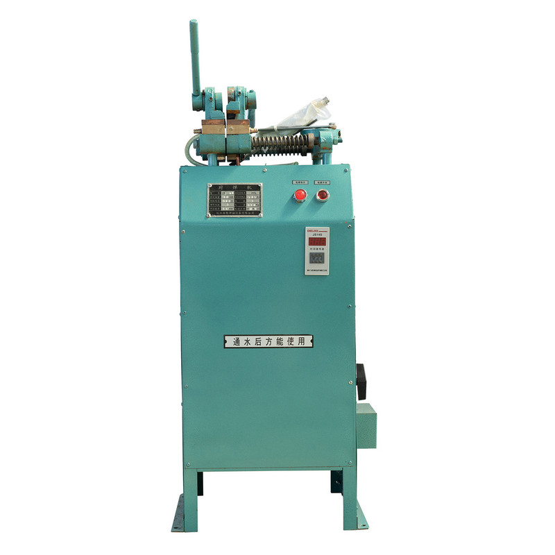
Within this category, gear-reduction designs improve on the basic lever mechanism. The DN1 Gear Type Foot-Pedal Spot Welding Machine uses a geared linkage to multiply the operator's foot force before it reaches the electrode arms, allowing thicker material to be welded without excessive physical strain. The gear ratio also smooths out the force curve, reducing the chance of an inconsistent clamp that leads to weak nuggets or expelled metal.

A pedal spot welder in this class is generally favored where electrical infeed capacity is limited, since mechanical units draw current only during the weld pulse itself rather than needing a separate compressed air supply line running continuously through the shop.
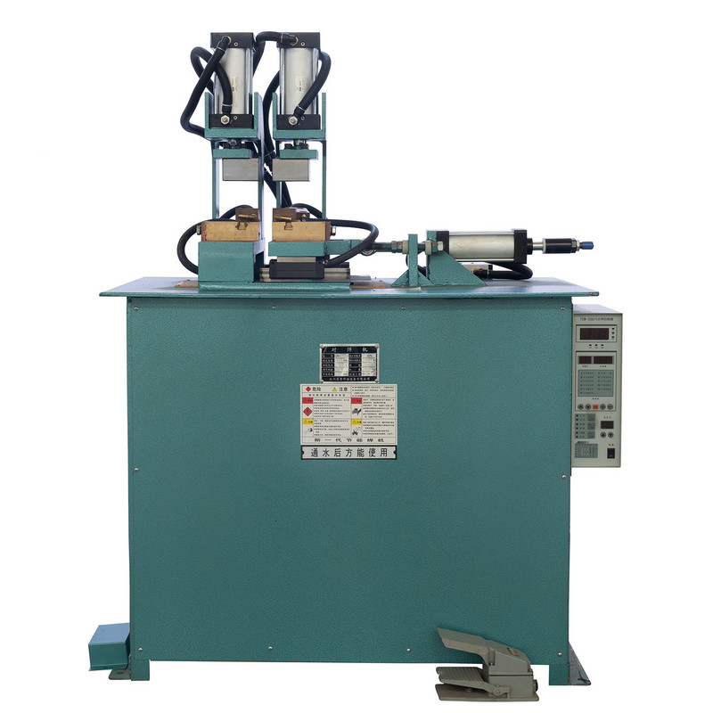
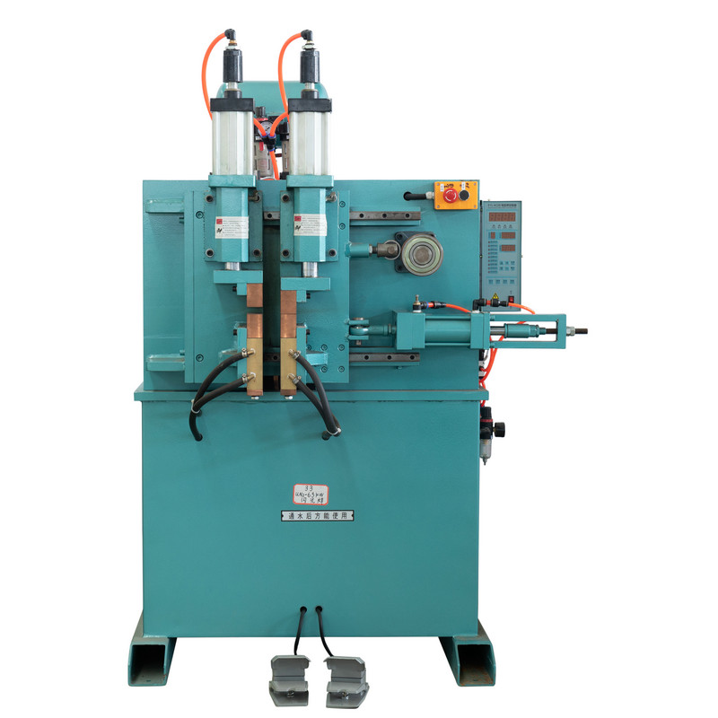
The DTN Pneumatic Spot Welding Machine replaces manual leg effort with an air cylinder that applies the same clamping pressure on every cycle, regardless of operator fatigue late in a shift. This consistency is the primary reason pneumatic spot welding dominates production environments where thousands of identical welds are made per day.
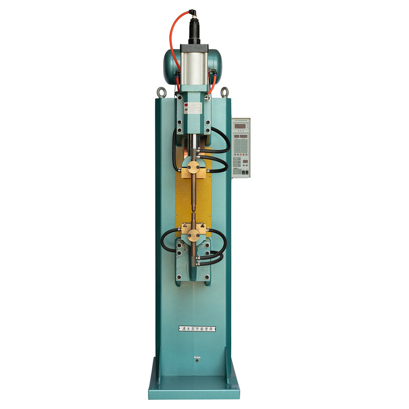
Because the cylinder stroke and pressure setting can be dialed in and locked, pneumatic units reduce the variation between the first weld of the day and the last. In practice this translates into fewer rejected parts during quality inspection, since nugget diameter tends to stay within a tighter range compared to hand-actuated pedal cycles performed over an eight-hour shift.
Each machine type trades off differently across six practical criteria that matter on a shop floor: force consistency, cycle speed, ease of use, portability, cost efficiency, and maintenance simplicity. The radar chart below summarizes these relative strengths on a common scale.
Electrode geometry has as much influence on weld quality as the machine itself. Selecting the correct spot welder tips for the base material and access angle prevents indentation marks, reduces current density hot spots, and extends electrode service life between dressings.
| Tip Style | Contact Face | Common Use |
|---|---|---|
| Dome / Radius Tip | Rounded, self-centering | General sheet metal, curved panels |
| Flat Tip | Full flat face | Coated or galvanized sheet |
| Pointed Tip | Narrow tapered face | Confined spaces, thin gauge trim |
| Offset Tip | Angled shank | Recessed joints, tight flanges |
Copper alloy tips remain the standard choice because they combine high electrical conductivity with enough hardness to resist mushrooming under repeated pressure. Dressing the tip face every few hundred cycles, rather than waiting until visible pitting appears, keeps resistance readings stable and avoids a gradual drift toward undersized nuggets.
Attaching threaded fasteners through resistance welding is a common requirement in enclosure and cabinet fabrication. Successful attempts to spot weld threaded studs depend on matching the stud base flange to an electrode holder designed for that geometry, since standard flat tips will not concentrate current correctly around a raised collar.
Undersized current settings are the most frequent cause of stud failure, producing a weld that looks complete visually but separates under moderate torque. A brief test cycle at the start of each shift avoids this outcome across an entire production batch.
Buyers researching spot welding machine price ranges often assume pneumatic units simply cost more across the board, but the real driver is transformer capacity and duty cycle rating rather than the force mechanism alone. A relative investment index across the three machine types illustrates the general pattern.
The additional cost of a pneumatic system reflects the air cylinder assembly, pressure regulation valves, and typically a heavier transformer needed to sustain faster cycling. For shops running under a few hundred welds per day, a mechanical pedal unit often reaches payback faster simply because the lower purchase price does not require a corresponding compressed air infrastructure investment.
Spot welding equipment spans a wide range of fabrication sectors, though usage concentration varies by industry. The chart below reflects typical distribution of spot welding tasks across common sectors.
Weld quality consistency naturally declines as electrode tips wear, but the rate of decline differs sharply depending on whether a dressing routine is followed. The line chart compares weld consistency across ten thousand cycles under two maintenance approaches.
The gap between the two lines widens steadily after roughly four thousand cycles, which is the point where an undressed tip typically begins mushrooming enough to reduce current density below the level needed for a full nugget diameter.
Rather than choosing based on price alone, a short structured process helps match spot welder equipment to the actual production requirement.
The final step, not shown separately above, is always a physical test weld followed by a peel or chisel check to confirm nugget penetration before committing to a full production run.
Shops that build a simple maintenance log, even a basic paper checklist tied to cycle counters, consistently report fewer unplanned downtime events than those relying on reactive repairs after a visible quality failure.
A pedal spot welder gives the operator direct tactile control over dwell time, which is useful on thin or irregular panels where an automated pneumatic cycle might overheat the material. It also avoids the need for a compressed air supply line.
Tips should be dressed well before visible mushrooming appears, typically every few hundred cycles depending on material and current setting, and replaced entirely once the dressed diameter exceeds the recommended maximum for that tip size.
Coatings and paint increase electrical resistance at the joint, so the coating should be removed at the contact point first, or current settings adjusted upward slightly to compensate, followed by a torque test to confirm bond integrity.
Not necessarily. Price generally reflects transformer capacity, duty cycle, and force delivery consistency rather than weld quality on its own. A correctly matched lower-cost mechanical unit can outperform an oversized pneumatic machine on light gauge work.
The most common causes are worn or mushroomed electrode tips, fluctuating air line pressure due to a shared compressor system, or incorrect dwell time settings for the material thickness being welded.
Recommended Products

Product
Contact Info.
+86-152-5712-5882
Fax: +86-563-2269966
No. 21 Guangping Road, Guangde Economic Development Zone, Guangde City, Anhui Province
QR Code